1.5 AMP PWM WALK-AROUND THROTTLE
revised Feb
2023
My most popular throttle - thousands in use worldwide since 1990 - now available in kit form!
Some of you will probably be asking " Why PWM?" and
"What's PWM?". The answer is efficiency. The majority
of model railroad throttles produce DC output voltage which is
more or less proportional to the throttle's knob position. While
there is nothing wrong with this in about 80% of the throttle's
upper voltage output, it tends to allow motors to heat more than
they really need to at slow speeds. This is due to slow ripple
voltage rise and decay times at low voltages. Sound a bit
technical? I'll explain a bit without getting too deep. Oh, by
the way, PWM is an acronym for Pulse Width Modulation.

|
The new model 852B handheld throttle
is a proven performer. Economy, performance and
reliability put this little marvel in a class by itself.
Well suited for comfortable HO, N, and Z scale one-handed
operation!
I know
of no other handheld throttle in the 852B's price range
that can out-perform it.
|
Let's look at a
rule of physics. "Things like to keep doing what they're
doing." If a locomotive is sitting idle with no power
applied, it's actually doing something. It's sitting there. When
you "give it the juice", a fair bit of power is needed
to get it going. Once it gets going you can back off the throttle
setting. Now it's doing something else. It's moving. To keep it
moving takes less power that it takes to get it moving.
Now, the funny
thing is that I have never seen a 12VDC motor start to rotate
with 1 volt applied to it. It might start to spin at around 3 or
4 volts. Once it starts to spin it will "jump" to life
and rotate. Now that it's rotating less power is required to keep
it going. You can even slow the RPM of the motor by decreasing
the voltage to it. But that same voltage setting would not be
able to get the motor spinning in the first place. With
conventional throttles at low voltages, something happens many
times per second. The throttle produces a dirty DC wave component
called "ripple". Ripple is a mixed blessing. It helps
to "kick" the motor around at low speeds but, the very
nature of the ripple component dictates that wasted energy at low
voltages is converted to heat in the motor windings as the motor
tries to overcome motor bearing friction, gear friction and the
weight of the locomotive itself. You can prove this with your
most stubborn locomotive. Try setting it on a piece of track and
turn up your conventional throttle until it starts to creep. Then
carefully back off the throttle until the locomotive
"stalls". Let it sit there for about a half hour or so.
Then pick it up. The safe money is that it's warm, maybe even
hot! That's because the voltage you've been feeding it for the
last half hour or so was not sufficient to get the motor spinning
and the motor is still working to try to spin. The energy
expended has been converted to heat. Wasted energy.
Pulse width
modulation throttles overcome friction and inertia by
"kicking" the motor with full throttle voltage for a
short period of time. The voltage rises to full amplitude very
rapidly and shuts down to nothing equally as fast. No slow rise
and decay times mean less motor heating. But even better, the
motor starts to spin immediately and PREDICTABLY. PWM throttle
settings produce repeatable and predictable speed changes without
jump starts and motor stall at low speeds. This means no more
overcompensating on the throttle control knob in the yard when
you're trying to couple to a cut gently or when you're trying to
take up coupler slack.
The
model 851's high impact styrene case measures only
4" X 2" X 1". The inside is packed with circuitry. No additional circuit boards need to be
installed. Simply wire it to an existing 12VAC to 18VAC
power source and to your tracks and you're in business!
|

|

|
Here's
the control board. It generates the PWM control and
momentum to give you absolute control of your
locomotives.
|
Miraculously,
all the required circuitry fits inside this little box!
Little, yes, but BIG on performance!
Unconditionally
guaranteed for one full year from the date of
purchase....try and get that from China!
|

|

|
The 852B is easy to connect to your layout. The 8' tether
cable's wires are color coded for identification and easy
hook up. 2 of the 4 wires go to your track, the other 2
go to the AC supply voltage source. Attach your own
connector for added versatility!
Now, how
much easier can it get?
|
A SHORT PRIMER ON PWM
Most of you will
be familiar with the concept of proportional voltage throttles.
But, what about PWM?. Take a look at the voltage pulse diagrams
below. When you start at the low end of the PWM control knob,
output voltage will rise from 0VDC (the blue dashed line) to full
output voltage (the red dashed line). This happens 60 times per second for
this throttle design. The
first wave is 10% pulse duration. This means that full DC voltage
is present for 10% of one sixtieth of one second. The pulse
duration is actually less at the bottom end of the control
setting, but 10 % is a nice place to start to explain what's
happening here. At the 10% setting the locomotive will be traveling at typical slow yard speeds. Turn it up to 25% and the
speed increases. The voltage doesn't increase, only the amount of
"on" time does. 50% and 90% settings increase the speed
of the locomotive proportionally. The throttle design presented
here varies the pulse duration from 0% (no voltage) to 100%
(which is pure DC) at full setting.
Real locomotives
use PWM speed control methods to turn their motors as do most
heavy industrial DC motors. Even VCRs, tape decks and CD players
use some form of PWM control to control motor speeds. Sadly, it
seems that poorly designed, cheap, proportional voltage control systems proliferate in
the world of model railroading.

If you have never
experienced the pleasure of absolute control in the operation of
a locomotive powered by a PWM throttle, you're truly missing out
on one of the better aspects of model railroading. It's kind of
ironic that people will spend upwards of $100 on the purchase of
a quality locomotive (just one? are you kidding?) and refuse to
dish out a few extra bucks to realize the full potential of their
new acquistion with a great throttle.
WANT TO BUILD IT YOURSELF?
HERE'S
THE DIY KIT VERSION
Yes, I'm pleased to announce that the new 852B circuit is replacing the old 851. The new circuit
has been designed with kit builders in mind and in the process of migrating the design I've managed to simplify construction. A complete kit of parts will be available
mid MAY 2011.
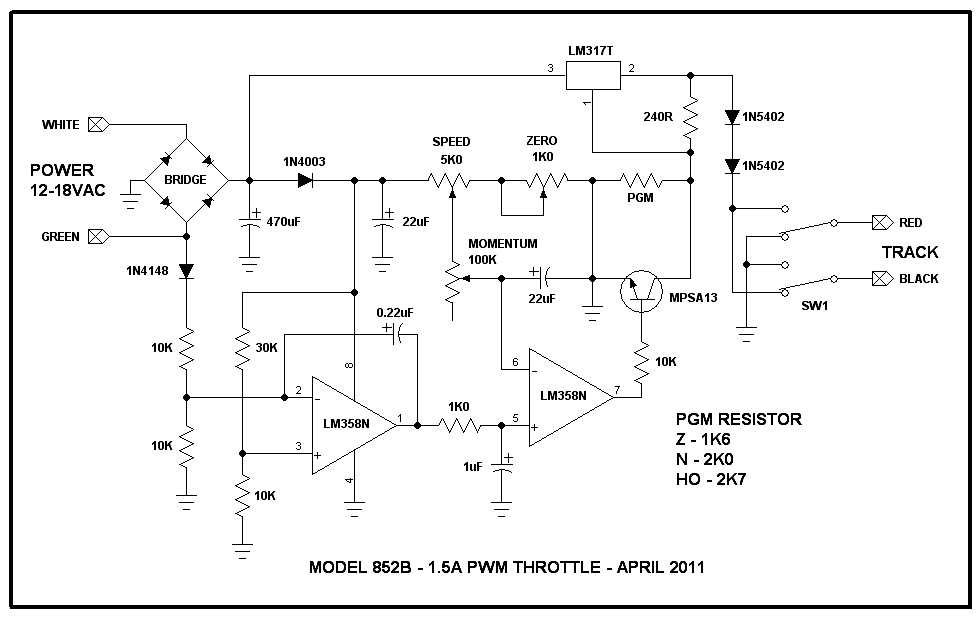
But... if you're bent on "scratch building" the new revised 852B schematic diagram is
below.
This throttle will
fit into a 2" X 4" X 1" ABS box as shown in the
photograph. It will dish out 1.5 amps at up to 12 volts
indefinitely. I won't get into
construction details. The schematic below shows all you need to
build one these throttles.
A neat thing about
the LM317T is that when they overheat due to excess
loading, they shut down and stay shut down until the overload is
removed from their output. This means that fuses and light bulbs
are not needed on the output. The output regulator needs to be
attached to a steel or aluminum heat sink as it will operate very
hot and shut down unless the heat is carried away from the
component. These regulators are virtually "bullet
proof"... ideal for model railroading!
The direction
change switch is a DPDT center off switch with at least 3A contact rating. The center off
function is nice if you need an "emergency" brake. It
also assures that the train comes to a stop before changing
direction.
POWER 12-18VAC are
the AC power inputs. Be sure to select a power transformer of
supplying at least 1/2 amp more current than the 852B is capable of delivering. This will allow the
transformer to withstand throttle overload conditions without
burning it's windings. By the way, this is called
"de-rating" a product selection. That means you're not
expecting the transformer to operate near it's limits. The
transformer voltage can be anywhere from 12 to 18 VAC.
PLEASE install the power
transformer carefully and safely. If you are unsure of electrical
safety practices, refer this installation to QUALIFIED personnel.
852B KIT DETAILS
The 852B kit comes with all the parts you'll need to build a complete 852B. The kit is universal
for all scales and "scale specific" programming resistors for Z (7.6VDC output), N (9VDC output) and HO (12VDC output) are all included. All you have to provide
are the tools and solder. This is a fun project and a great way to save a few bucks as well as a great fund raiser for clubs! Try selling a few assembled kits at your
next club open house or swap meet!
The instruction set is very comprehensive and is targeted to intermediate kit builders. A novice
may require some guidance. Kits take 1 hour to assemble.

PRICING SCHEDULE
|
MODEL |
DESCRIPTION |
QTY |
PRICE EACH - USD |
|
852BA-(SCALE - Z - N -HO) |
ASSEMBLED & TESTED 852B PWM THROTTLE |
1-3 |
$45.00 |
|
|
|
4-8 |
$43.00 |
|
|
|
9-25 |
$39.00 |
|
852BK |
KIT FORM 852B PWM THROTTLE |
1-3 |
$32.00 |
|
|
|
4-8 |
$30.00 |
|
|
|
9-25 |
$27.50 |
FOR QUANTITIES IN EXCESS OF THOSE LISTED PLEASE CONTACT ME
SHIPPING
EXTRA
To order this item, send
an e-mail to me and I'll
supply you with details.